Some time back I started work on a conversion project where I took the
1/100 Scale Heavy Arms Custom Kai from Endless Waltz, and convert it
into something more like what appeared in the Anime series. I had
finished the project some time ago but hadn't had a chance to finish the
review video of it. Well it is up now!
Monday, November 23, 2015
Wednesday, November 18, 2015
Wednesday, November 11, 2015

So with a finished project, what problems did I encounter working on it? Well the legs are the first thing that stick out. I mounted the feet too far apart on the Libra base, so this forced the legs further apart. This creates a bit of a bow-legged appearance and hurts the final version of the model.

Monday, November 09, 2015
So now we're starting to wrap up this project. Wow has it ever been a trip to get to this point, from experimenting with casting clear resins, to building new sections to replace what would otherwise be moving joints, to modifying existing parts to accept new components. Now it all begins to come together.
 It was a fairly simply matter to cast a new part for the chest gem. I simply attached the original gen sticker to a segment of styrene tubing, and then made the mold based on that part. Unlike casting the saber effect, this was a far simpler affair and required only 2 attempts to get right including embedding the LED in the part.
 Of course putting everything together... that was more of a chore. Here you see the majority of the final connections being made in the chest cavity.
 I should have thought of this before, but alas I did now. The way the model is intended to transform, there is a slot in the back where the hip/waist assembly would fold up allowing the legs to flip over the back. Since I removed the actual transformation mechanism, this space was no longer needed and I really should have covered the slot with styrene and painted it to match the rest of the waist. Sadly this wasn't something I thought of before hand. So if you look closely you will see the wires in the finished model.
 "What? you think I was going to skip arm day?"
I had to use pressure clamps to hold the body together while the glue set. This is largely it. Next time the finished project.


I had to use pressure clamps to hold the body together while the glue set. This is largely it. Next time the finished project.
Friday, November 06, 2015
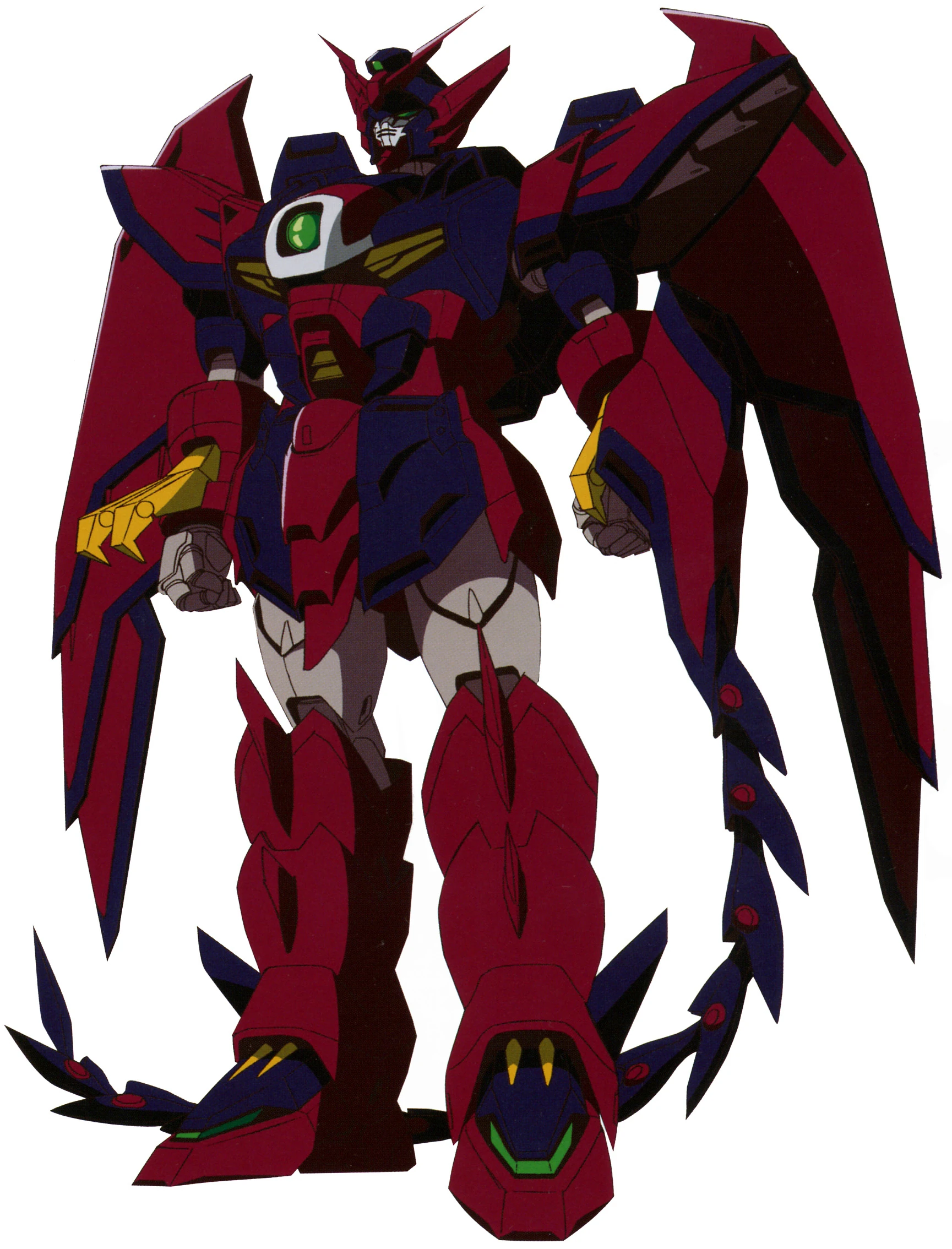
So today I'm talking about fabrication. One of the major features of the Gundam Epyon is its ability to transform from mobile suit mode:
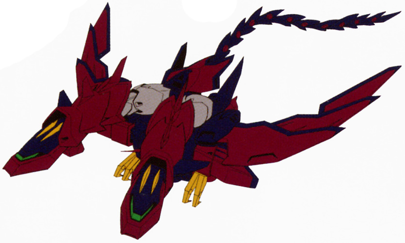
 to a twin-headed dragon style mobile armor:

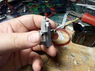
 I used a series of styrene tubing I built up a central section that would pass up through the assembly, and then glued a section of 1/4" styrene block into the space behind it. This combination provided a solid base to firmly attach everything together and effectively remove the entire transformation mechanism.

 There were 2 other sections that I chose to make non-moving, the elbow joints. See in the standard model the elbows are made by joining 2 pvc joint pieces so that it will have a 2 axis range of movement. While this is nice, it doesn't help for this project. So I went to work building replacement joints that would be glued into place.
 I started with segments of 1/4" styrene blocks and drilled out holes to accommodate the mounting pegs of the fore arms. I then passed segments of tubing through the upper portion of the blocks that would match the mounting holes in the upper arm. I added some groove slats to the back side of the sections to add some visual detail. With the parts glued in place, some paint finished the fabrication.

This gimmick is carried over to the model itself and is managed by way a
splitting hip/waist assembly. As far a gimmick trick it's a nice setup,
but for my purposes it creates some issues. Specifically the risk of
the hinge joint causing the electrical connections to be broken after
assembly of the model. So I had to address this by either gluing the
hinge shut or reinforcing it. I elected to do both:


Wednesday, November 04, 2015
I knew from the start that the giant beam saber was going to be a critical component of the finished model. I wanted the entire saber effect to glow bright green and that was going to be a challenge. At first I toyed with the idea of inserting a flat LED into the base of the saber effect and running wires through the hilt and into the hip.

While there was ample space to place the LED in the base of the saber effect, there was the issue of connecting it to the power source. I felt a bit nervous about trying to solder the connections so close to the hilt. So I decided to go with resin casting with the intention of being able to embed a string of LEDs into the saber effect.
Yeah... working with translucent resins and dyes is trickier then it first seems.


It is a very solid and very nearly totally opaque red. It looks kind of cool, but it wouldn't work for my purposes. I did try putting a super-bright LED to the red resin just to see how much light did come through. In a totally dark room, with not other light sources what so ever, it just barely glowed at all. Far too dark for what I was going for. So I went back to experimentation working with differing concentrations of dye in the volume of resin. I used rock molds to avoid wearing out the saber effect mold I had made.

I finally settled on an approximate ration of resin to dye by mixing up 1 1/2 ounces of resin and adding about half a drop of dye from the very tip of a pin. Yeah when they decided to call there dye series 'So Strong' they picked the right name. With a good ratio figured out, I went to work building the LED array to embed in the cast. I settled on a series of four flat LEDs to get the proper brightness. It took some finagling, but I managed to get the LEDs roughly in the middle of the mold and the resin properly cast around them.


Monday, November 02, 2015
"Hey Zecks, Zero is saying you have no future. Is Epyon telling you different?"

So today I'm talking about the head. Since this a basically humanoid model, you know if you ignore the large wings, the devilish appearing armor and the whip arm that is, the head is a major focus point for the model. Because of this I wanted to put extra care into it's production and preparation.

The first challenge was making space for the LED in the head. I went with a flat topped LED because it's easier to orient. To help direct the light more I painted the back side with silver pant and then came back with several coats of black paint. I wanted as little light leaking out as possible. In order to accommodate the LED in the head I had to cut away the mounting ports that would normally hold the parts of the head together. The next big trick was building a new neck brace for the head.
Normally the head sits on a ball joint, but with the LED in there the joint would have have to go. So I went to work with some styrene tubing and built a new mounting brace. I took extra care to ensure the negative and positive leads on the LEDs are on the right and left respectively. This way it was going to be easier to connect everything later one.
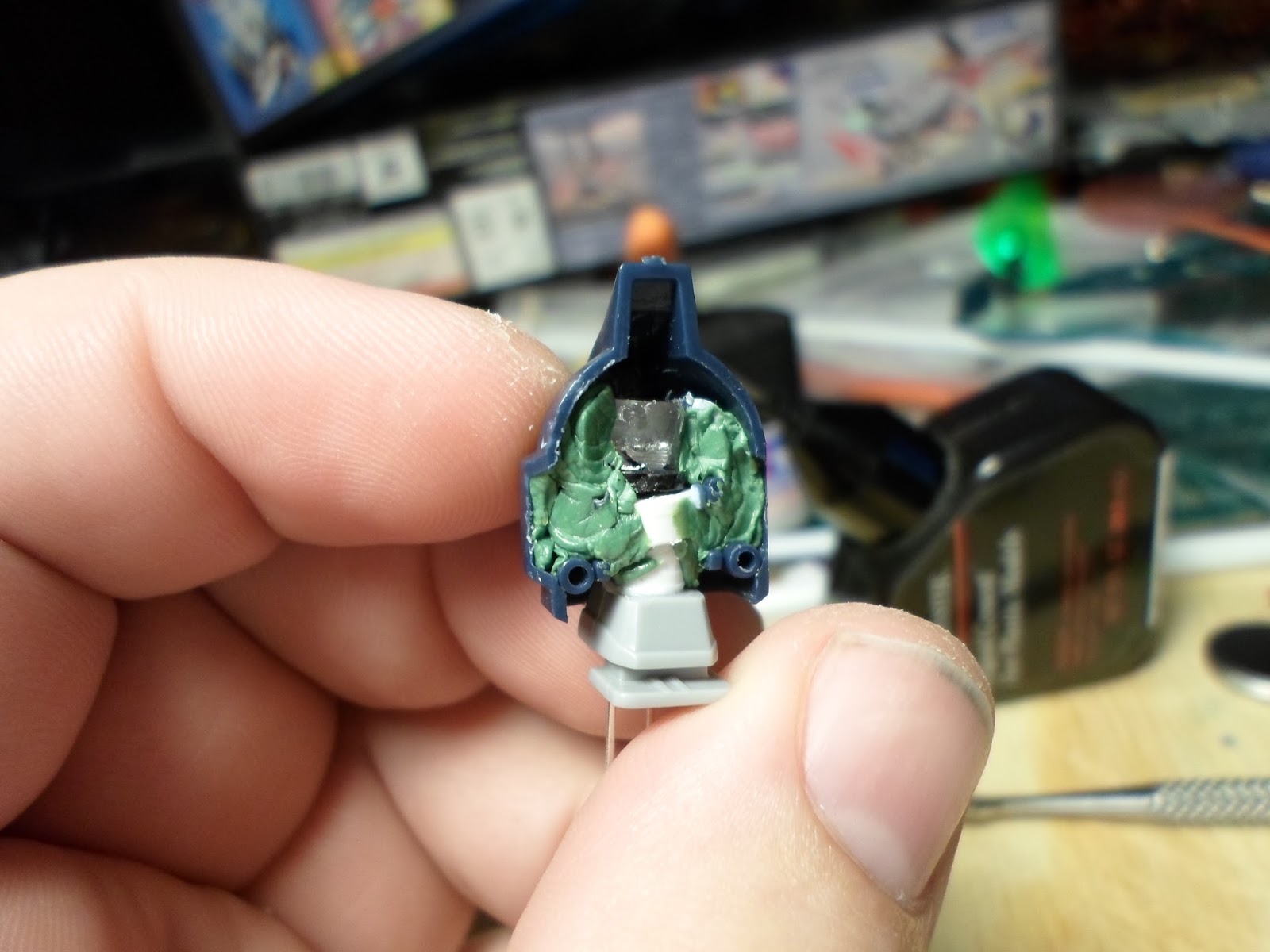
Once the new neck was built, I went back in with some Kneadatite modeling putty and filled in the space. I do not want this LED to move at all.

Saturday, October 31, 2015
So yeah. There's a blogger plug-in for FaceBook. It says it will take what you post on FaceBook and repost it on your blog. Guess that hasn't been happening. Sorry for that everyone. I'll make it a point to post here as well as on FaceBook. Just as a reminder you can follow me on Facebook and on Twitter. At least that way I know they're both updating.
So what have I been working on? Well, a lot. Far more then I should be talking about in a single post. So here is what I'm going to do for the next couple weeks I'm going to make posts on Monday, Wednesday, Thursday and Friday! So stay tuned for the next couple weeks.
So what have I been working on? Well, a lot. Far more then I should be talking about in a single post. So here is what I'm going to do for the next couple weeks I'm going to make posts on Monday, Wednesday, Thursday and Friday! So stay tuned for the next couple weeks.
Monday, June 15, 2015
If you follow me on Facebook and/or Twitter you most likely saw a message a few weeks ago about my projects being on hold until I got a new tool rack. Well I have gotten the new tool rack. Specifically I have built a new back board for my work space, along with a few other new pieces of equipment as well.

This is my newly revamped work space. What? not impressed? Oh confused about some of it. Well that's no problem because I intended to talk about it.

So the first big thing, the work mat. Previously I just had the Hobbico mat sitting on the table top. Which was fine.... right up until I needed to use a speed square or needed a solid edge to align against. 1/8" thickness doesn't give me a lot to work with. So I mounted the cutting mat to a section of 1/2" plywood. This helps keep the cutting mat up off my table top surface, while still preventing the mat from slipping or sliding while I'm working on it. it also provides a hard edge to align the speed square and carpenter square against.
 The second thing is I build a back drop to the work space. There's an open shelf behind that wall but it's lays so far back relative to the depth of the work space that it makes using it for storage... dubious at best and I've lost more then a couple pieces of models down the void that is the opening between the back of the table and the front of the shelf set. I also put in a bunch of hooks to act as tool mounts for many of my more commonly used, or more likely to do damage/be damaged if I put them in a drawer, tools.
 One of the biggest problems I was running into was not so much storing my tools, as storing them in a meaningful way. As an example, my files. Putting them a 6" deep drawer makes then fairly hard to find later on. And very frequently stuff would basically vanish and I would assume I had lost it, and then buy a replacement only for the original one to show up weeks later. So by making this divided drawer, I have a ready space to put these tools and there simply isn't enough space to pile a lot of stuff on top of them and loose them.
 I purchased a new work lamp for my space as my previous one was getting up there in age and down there in terms of usability. The mounting joint for the head wouldn't stay anymore so I had to use the electrical cord to hold the light up which also meant it was stuck in basically one position. The Other joints were loosening as well so the lamp was developing a tendency to slump. Short version, the lamp was wearing out.
The new lamp has new joints with rubber meshing in them so it's sturdier and better able to stay in a given position. It also has a magnifying lens built into the head lamp as well. As an added piece of versatility, I built a new base for the lamp. Made from a section of 2x4 lumber, with a series of 1/2" copper pipping counter set into the wood I have different positions I can place the base of the lamp and still have it stay put on the work space surface.
 Finally we have this fun little contraption. What is this? Why it's a ceiling mounted articulated camera boom arm of course!
What? Don't know what a boom arm is? Oh, well let me explain. The short version is a boom is used when you need to hold something like a camera in a position or spot that you don't otherwise have the means to hold it. This could be because of distance, or it could be something as simple as "I don't have someone else to hold it!" In my case it's closer to the latter. See this boom arms is mounted over top of my work space and because of the articulated nature of the arm, I can position the camera that is mounted on the arm in a variety of locations and angles. This will be useful when I'm doing videos and I need to do an 'Above the work space' shot.
This is my newly revamped work space. What? not impressed? Oh confused about some of it. Well that's no problem because I intended to talk about it.
So the first big thing, the work mat. Previously I just had the Hobbico mat sitting on the table top. Which was fine.... right up until I needed to use a speed square or needed a solid edge to align against. 1/8" thickness doesn't give me a lot to work with. So I mounted the cutting mat to a section of 1/2" plywood. This helps keep the cutting mat up off my table top surface, while still preventing the mat from slipping or sliding while I'm working on it. it also provides a hard edge to align the speed square and carpenter square against.
The new lamp has new joints with rubber meshing in them so it's sturdier and better able to stay in a given position. It also has a magnifying lens built into the head lamp as well. As an added piece of versatility, I built a new base for the lamp. Made from a section of 2x4 lumber, with a series of 1/2" copper pipping counter set into the wood I have different positions I can place the base of the lamp and still have it stay put on the work space surface.
What? Don't know what a boom arm is? Oh, well let me explain. The short version is a boom is used when you need to hold something like a camera in a position or spot that you don't otherwise have the means to hold it. This could be because of distance, or it could be something as simple as "I don't have someone else to hold it!" In my case it's closer to the latter. See this boom arms is mounted over top of my work space and because of the articulated nature of the arm, I can position the camera that is mounted on the arm in a variety of locations and angles. This will be useful when I'm doing videos and I need to do an 'Above the work space' shot.
Friday, June 12, 2015
Oi Vey... This has been one muther of a project! And I'm not done yet. Still waiting for some parts to come in before I can finish it but I can talk about it.
 This project has been so incredibly involved that I'm not actually sure where to start with it. The base was it's own special adventure, while building the main body of the machine was practically a project unto itself. So let's start by talking about the base.

As I explained previously, I wanted the Knight to be crushing or standing on something. Something is iconically dangerous. I settled on the body of a Carnifex for this purpose. Carnifexes had long been the "Big Baddies" of the Tyranid army, on a part with Dreadnoughts and able to take utterly horrendous amounts of punished. Well up until 5th edition anyway. Though even in 5th, a Carnifex isn't something you want to ignore. So I put a battered and beaten Carnifex body on the base. The base itself is the Knight Titan sized base from the Goth Teck series by Dragon Forge.
So I got a Carnifex and assembled the main body but not the head. In order to mount the body on the base I ran it across a surface sander for a few seconds to give it a flat side. With that accomplished I mount the body on the base with a combination of pinning and super glue. With it properly mounted I used a hair dryer to soften the plastic of the tail and flex it a bit to give it a more "dead" look to it.
I knew I wanted to distress the body and show battle damage to the Carnifex so that was my next step. For this I fist went to town with a 3mm drill bit and bore out several holes in a pattern to suggest automatic weapons fire. I applied the holes to the back of the armor and across the side of the body. I wanted to make it look like it had put up some sort of a fight. Once I had the holes bored out, I came back with my exacto blade and scored up the edges of the holes and carved cracked into the armor around them. Then I went to work on the head. I used my pin vice to add some bullet marks to the head crest and then to bore out the eye socket of the Carnifex.

 Finally I attached the head to the body in a slumped own position to show it's dead as a door nail.The big thing I needed to do in order to sell the entire "Stomping on the dead body" I needed to quasi-level out the back a bit and show some distress and breakage from something the size of a knight titan crushing the back of the Carnifex. In order to accomplish this I took a razor saw and some needle nose pliers to the back armor and made a combination of bends and breaks in the armor to accept the flat foot that was too come.
The big task to accomplish with the base was ensuring there was sufficient space to house the battery pack, wires and switch for the lights. Originally I was going to use a 2032 dime-cell battery to power the circuit, but the battery pack for such a battery has exposed leads. I ran into a problem with these as the glue or modeling putty tended to interfere or even break the exposed connections. So I opted to use a AA battery pack even though it takes up more space. The Dragon Forge base isn't deep enough to accommodate something on the scale of a AA battery pack so I needed to find another solution. I found it by making an exploratory trip through a Michael's craft store where I found an oval wood base only slightly larger then the diameter of the knight base. So with the wood base I was able to route out a space for the battery pack, the switch itself and the wire leads.

As I explained previously, I wanted the Knight to be crushing or standing on something. Something is iconically dangerous. I settled on the body of a Carnifex for this purpose. Carnifexes had long been the "Big Baddies" of the Tyranid army, on a part with Dreadnoughts and able to take utterly horrendous amounts of punished. Well up until 5th edition anyway. Though even in 5th, a Carnifex isn't something you want to ignore. So I put a battered and beaten Carnifex body on the base. The base itself is the Knight Titan sized base from the Goth Teck series by Dragon Forge.
So I got a Carnifex and assembled the main body but not the head. In order to mount the body on the base I ran it across a surface sander for a few seconds to give it a flat side. With that accomplished I mount the body on the base with a combination of pinning and super glue. With it properly mounted I used a hair dryer to soften the plastic of the tail and flex it a bit to give it a more "dead" look to it.
I knew I wanted to distress the body and show battle damage to the Carnifex so that was my next step. For this I fist went to town with a 3mm drill bit and bore out several holes in a pattern to suggest automatic weapons fire. I applied the holes to the back of the armor and across the side of the body. I wanted to make it look like it had put up some sort of a fight. Once I had the holes bored out, I came back with my exacto blade and scored up the edges of the holes and carved cracked into the armor around them. Then I went to work on the head. I used my pin vice to add some bullet marks to the head crest and then to bore out the eye socket of the Carnifex.
The big task to accomplish with the base was ensuring there was sufficient space to house the battery pack, wires and switch for the lights. Originally I was going to use a 2032 dime-cell battery to power the circuit, but the battery pack for such a battery has exposed leads. I ran into a problem with these as the glue or modeling putty tended to interfere or even break the exposed connections. So I opted to use a AA battery pack even though it takes up more space. The Dragon Forge base isn't deep enough to accommodate something on the scale of a AA battery pack so I needed to find another solution. I found it by making an exploratory trip through a Michael's craft store where I found an oval wood base only slightly larger then the diameter of the knight base. So with the wood base I was able to route out a space for the battery pack, the switch itself and the wire leads.
Monday, June 08, 2015

Last time I talked about the first part of the process of
air brushing the parts for this kit, priming them with the Vallejo
acrylic-polyurethane surface primer, pre-shading the parts and then applying
the base color of green on the model. So what’s next? Well now we’ve got the
second color of green to apply to the model, which means I need to talk about
masking the model parts.
Ever paint a room but want to have the trip a different
color then the rest of the room? What do you do? You use painters tape to put
down a barrier so the two paints don’t go where you don’t want them to go.
Masking is basically the same thing. It’s the process of taping off a part to
ensure the paint doesn’t go where you don’t it to.


I attempted to fix my error by coming back with the original
green paint and brush painting to cover up the black bleed over. Well, brush
painting doesn’t put the paint on the same way the air brush does. So the colors
don’t exactly match. That’s why there’s
the hard line of different colors on the thigh of the model here. So not a
perfect cover up but this project was all about learning so as long as I can ID
the problem and look at why the problem occurred I’ll call it a win since it’s
something I can avoid doing next time.
So with the air brushing done I moved on to assembly. And
this is where I noticed a fairly large error I had made early on. The left leg.
More specifically the inner assembly of the left leg. See the inner part of the
leg is a support strut that serves as the ankle and the mounting for the front
and back of the lower leg itself. The pieces are specific to the right leg and
left leg respectively AND they have to go in the right way. So what did I do?
Well I put the left foot on the right strut with the strut itself upside down.
Ouch. So what did I do? Well I have glued the parts together so I couldn’t just
pop the parts apart and switch the parts. Now the problem here is that I couldn’t
actually tell that the wrong feet were on the wrong struts, at this point I
only knew that I had put one strut in upside down. So I used my pin vise to drill out the
mounting point for the ankle, cut away the few remains of plastic that was
keeping the foot on, and turned the strut around while using a piece of styrene
rod to rebuild the ankle joint.

So with that leg taken care of, I proceeded to continue
assembling the kit. Well here is where I found my largest learning point
regarding air brushing. Not so much with the technique, but in regards to
planning. See Airburshing doesn’t put down a truly uniform layer of paint. The
differences are very hard to see when it’s one continuous application across
one part. But I didn’t assemble the parts, beyond the feet and the mounting
struts for the legs, before painting them. So what does this mean? Well here is
a good example:

The front part of the shoulder armor is a lighter green then
the back half, even though they were painted at the same time with the same
paint from the same air brush. This is because of the non-uniform application
of the paint combined with the uneven application of the black paint in the
pre-shading stage. So planning your build relative to how you will paint the
kit is a necessity when you’re working with an air brush.


Nothing was substantially different here from what I did
with the Gouf save that I didn’t use any white pigment since the Zaku II was primarily
a space based mobile suit. Don’t see a lot of concrete in space after all. I mainly
used the black and grey pigments to add shading and dirt to the model. The
additional discoloration added some more definition to the model.
As an attempt to address the mis-matched feet problem I
built a flying stand for the model by cutting a length of brass rod, mounting
the rod on a platform and then drilling an accompanying hole into the crotch of
the model itself. This allowed me to position the model as if it were floating and
mostly hide the feet.
So a 30-something year old model. First real usage of an Air
brush. Applying weathering Pigments. And finally addressing several mistakes
and errors. Overall I’m glad I did this project. It has been a worthwhile
education and was a real challenge over all.
Friday, June 05, 2015
So I built a 30 year old model kit, the 1/144 scale MS-06
Zaku II. I don’t have an exact date of production for the model kit, only a
rough idea that it is a ‘first generation’ of Gundam action figure model kits
that was produced prior to 1985 but after 1980. So the kit is somewhere between
35 and 30 years old. Now I have built several Gundam model kits in the past,
but the oldest one I had ever built was from the mid-90s so this was a radical
departure from my previous experience in the medium.

Preparing this kit for airbrushing was an involved process which started with cleaning the parts in warm water with a little dish soap. I used a tooth brush to clean off any remaining mold release, which considering the age of the kit I would be shocked to actually find any. Still cleaning the parts is always a good idea and triply so if you intend to paint your kit in any form. Once I cleaned the parts I left them out to dry over the course of a week end.
After making sure they were dry I came in with my air
compressor and blew off any dust that as accumulated on the parts. Then I went
to work prepping the parts with various grades of sand paper. Starting with a
700 grit sand paper I made work across all the surfaces of the model. I then
came back with 1000 grit and cleaned that up, then followed that with 1500 grit
and then finally finished up with 2000 grit sand paper.
All of this was to help clean up the surface of the model in
order to properly air brush it. Here we can see an example of a part before it
was painted in the acrylic-polyurethane surface primer.

It’s sort of a slightly too-bright German camo-green. Which
kind of works giving the coloring of the Zaku II from the tv series. Painting
the parts comes in a series of steps, the first of which is coating the part in
a smooth but even coat of white primer. The second step was using a black paint
to pre-shade parts of the model. Here you can see an example of a part that has
been pre-shaded.
 Now I will admit I’m new to air brushing, and I will admit
to the possibility that my understanding of some of the techniques is wrong, so
if you hear something different from what I explain right now don’t be
surprised if it’s different. Also, please post a link to the info below in the
comments. The entire point of this website is to promote learning and
experimentation with models. Now, as I was saying, pre-shading is a
process to produce shading and color variation with a model by making use of
the transparent qualities of paint. By putting down the white primer coat, and
then using the very dark paint to shade sections of the model, the later colors
will be darker in those areas while being light where the black paint isn’t
present. The best example of the end result I can show is here on the shoulder
shield:
Now I will admit I’m new to air brushing, and I will admit
to the possibility that my understanding of some of the techniques is wrong, so
if you hear something different from what I explain right now don’t be
surprised if it’s different. Also, please post a link to the info below in the
comments. The entire point of this website is to promote learning and
experimentation with models. Now, as I was saying, pre-shading is a
process to produce shading and color variation with a model by making use of
the transparent qualities of paint. By putting down the white primer coat, and
then using the very dark paint to shade sections of the model, the later colors
will be darker in those areas while being light where the black paint isn’t
present. The best example of the end result I can show is here on the shoulder
shield:
I applied the pre-shading to the shield largely because the
shield was otherwise a flat and visually un-interesting surface. Adding the
pre-shading helped to break up the plain-ness of the shield. I worked to apply
the pre-shading to the majority of the parts, which required that I assemble a
means to hold all the pieces between stages. This was accomplish by making a
series of mini-mounting arms using small clips and tooth picks. The tooth picks
were then mounted on a block of floral mounting foam. This allowed me to
quickly switch between parts to paint, while not needing to actually touch the
piece.

Subscribe to:
Posts (Atom)