Showing posts with label Sheet Styreen. Show all posts

Monday, January 21, 2013

Well some busy work

So There's not much I can do with the Thunderbolt right now. Not until I get the new supply of Mold Compound which isn't going to happen for a little bit. Need to recover from the medical expenses. But one thing I don't do very well is nothing. I can't not be working on a project of some form. It just doesn't happen for me. It may not always be War hammer related but I am working on something.

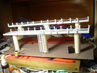
So today I decided to take a cue from a friend and fellow blogger, Virtual Stranger. He runs "In the Grim Cheapness of the Future" and has served as something of an inspiration for my own scratch building adventures a couple of times. So what direction did I take form him? The cheap ass one! I decided to see what I could with what I have on hand. Now with a bitz box the size of the one I have I could probably pull together enough parts to build something on the scale of a land raider if I really wanted to, but I have enough models for the time being. I don't need to build more random ones. So I decided to shift gears a bit and try something in the terrain category. I got a series of videos from MiniWargaming.com a while back. I don't recommend their videos as basis for learning new techniques, as they are rather caviler with their explanations and directions about what they are doing and there have been a lot of times they've just blown through a major chuck of the project and I'm left scratching my head trying to understand what the hell they just did. Like wise they're words regarding safety is painfully lacky and frequently limited to "Just be careful you don't cut your self."  There are a lot of times in the videos where I feel the need to reach into the video and hold up a sign that reads "Do NOT do this the way I am doing it. It is not safe.!" Their videos are definitely geared more toward the veteran hobbyist then the young blood. But they do have some ideas that are worth wild. One video they did is constructing an industrial catwalk using 1/2 pvc plumbing pieces as the basis for it.

The project is rather straight forward and uses a handful of materials. Most of which I had one hand. I made 3 alterations to their project in my rendition of it.

Firstly, I filled the PVC tubes with resin and then attached the catwalks to the piped by counter sinking a screw into the resin in the pips and then pouring resin into the squares under the catwalk platform. This helped secure the entire structure.

Second, I attached long segments of angel bracket to the sides of the catwalk, covering the edges of the diamond plate and giving it a more "This is intended to be walked on by normal people" look to it.
The angel bracked on the edges of the walk way.


The third thing I changed was a partially a matter of convenience partially one of preference. I used an enclosed ladder cage on the lower segment of the walk for the ladder. I grew up around military bases and one thing I always saw a lot of were "Off limit" warnings and safety mechanisms. In the real world these cages are put on ladders to prevent people from falling back and off of the ladder. Yes it's still possible to fall down and have the cage make no difference what so ever. But then you get into the realm of "How did you live long to get hired for this job?"

 I thought this would add a little bit of realism to the piece. Plus I had the material on hand and didn't have to get it.
The nearly finished catwalk
With the exception of the Light diffuser, base board, and plumbing parts, all of which can be obtained from a hard ware store for about $25, all the materials in this project can be obtained through Plastruct and EverGreen plastics.

Sunday, January 06, 2013

thought I'd provide some information

As I've previously stated my work on the thunderbolt is more or less on hold until I get more materials. I can still work on small details and I am, but I can't make any major head way on the body until I get the materials to cast the molds of the engine mounts. So I've already ordered them so now it's just a waiting game. In the mean time I thought I'd post some information about the materials I'm using for this project.

The first thing is obviously the Styrene, or plastic, materials I'm using. For the large part, the majority of my styrene is coming from Plastruct. They've been around for a while and offer a truely staggering array of extruded styrene shapes and forms. I've also purchased Styrene from another company called EveryGreen Scale models. Their selection isn't as huge as Plastructs', but they have some stuff that Plastruct doesn't.

Take a look at the engine master I built. As I previously mentioned, it's a series of tubes set into one another with other detail added to that.
the scratch built master of the back section of the engine

Here is a structural break down of what I used to build the engine master:
the exploded view diagrame of the back section of the engine
Because I will be referring to different sizes, I have color coded this passage to match with the diagram. The green tube is a length of Plastruct's TB-24 piping, which is measured at 19mm outside diameter. The pink is TB-28 tubing and measures at 22mm. The blue, which slips around the forward most length of TB-28, is a segment of TB-32 and is the largest piece of Plastructs inventory of piping I've needed to order yet. It measures in at 25mm outer diameter. The sea foam green 'C' is a wrap of textured plastic from EverGreen's assortment. The precise one I used in this case is listed as E-5 '4529' "Metal Siding" and is sold in sheets of 100 square inches. Apply a little bit of heat and it becomes pliable and can simply be glued into the length of TB-28.

The floating yellow squares are just panels of .5mm thick styrene I cut and glued to the last section of exposed TB-24. The teal length between the segments of TB-28 are simply lengths of 1mm thick Hex-rod. Plastruct's got these listed as MRX-60. I also got .1mm lengths of these hex rods to become the bolts on the sides of the engine you see in the finished product.

And that's the breakdown of how I built the master for the back half of the engine.

The forward intake was a similar process but needed some innovation to accomplish.
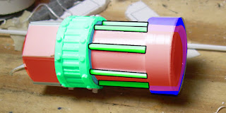
exploded view of the intake section of the enginethe scratch built intake for the engine

Like with the back section of the engine the intake housing is built out of 2 lengths of pipe set into one another. The inner section, shown in pink is a length of TB-28 while the blue is a length of TB-32. The red is a disc of 1mm thick sheet styrene. For the intake blades I had to get creative. I make 4 discs of .1mm thick styrene, the same diameter as the inside of the TB-28. I then cut those dics into 8 segments, like a pizza. Then I glued down each blade seperatly so that each successive blade was over half of the previous one. I had to get a little fiddly with the last two or three in order to get them to line up properly but it worked out. Then I took a hold punch that measured just under 5mm in diameter and punched out the center of the assembled fan blades.
I then took a length of Plastruct's MR-190 5mm rod and sanded one end down to a rounded nub and then put that through the hole I made in the fan blades. To help simplify it all out I attached a scrap piece of styrene to back of the .1mm disc.

And there you have how I build the engine masters for the thunderbolt fighter.


Friday, January 04, 2013

Delays....

Well I've hit a little bit of a delay in work on the thunderbolt. Namely I need to wait for materials to come in. Yes, I am out of molding compound and had to order more. Hopefully the order will be in sometime early next week. For whatever reason I can not fathom, I am able to get reactive compounds, that have been used in the production of IEDs from over seas faster then I can order plane old sheet of sheet styrene from with in the continental US. Anyone else have that sort of... oddity in their country?

Anyway, I had actually managed to get a fair amount of work done before I realised I was out of molding compound.

The engine master, the main engine piece, the engine mounting block, engine detailing for smash casting, and the air intake for the engine.

As you can see there are 5 components there, well okay maybe you can't see all 5. There's the engine master on the left, behind that is the central engine that will go into the main body of the Thunderbolt. On the ceramic tile is the engine mount on the back, that big block looking thing. The intake for the engine closer to the camera and then to the left of the intake is another piece. it's really hard to see but it's the master for a detail piece I'm going to smash cast to apply to the engine master before i cast the copies of the engine.

I test fit the central engine earlier:
test fitting of the main engine in the body
It does fit but I'll need to put material in the body to secure it. As it stand now it's just too damned heavy for a couple dabs of plastic glue to secure it. I'm considering filling the body with resin and using that to secure the engine housing. Not only will that secure it, but it will also make the body very strong and resilient to being handled.

Wednesday, January 02, 2013

New update on Project Thunderhawk... er bolt... thunderhawk bolt

Okay so I'm not sure what I'm calling this project anymore. I'm still intending to build a Thunderhawk, but the case-study of building a Thunderbolt has really taken on it's own life and become a project onto itself. Regardless I am making progress. One of the key points I was planning on under taking in building the Thunderbolt was scratching one engine and then casting two copies of it for the finished model. Well, I've finished building the original master:

the scratch built master of the engine
The engine itself is build with a long central tube, and several larger segments of tubing glued to the body. I'll explain in more detail below.


color coded break down of the engine

The red is a single long tube measuring 5 centimeters. if you look at the front you'll see 2 colored rings, one purple and one blue. Those are each another ring of piping affixed to the tube. The green ring further back is another segment of tube the same thickness as the purple tube at the front, but this one has a layer of roof textured glued to it. Then the green and black segments in the front are lengths of hex rod glued in place.

The way the template has the engines, they are built in 2 parts and then each affixed to a box on the side of the main body. Here you see the scratch built air-intake and the main engine housing.
I have some details to add to the master before it's ready to cast but it's all repetitive details, items that appear in multiple places on the finished model. So what I'm going to do is quick-cast a mold of the master of the detail part, then with the finished mold use green stuff to cast copies of it that can then be affixed to the engine master. With a little luck, I'll be posting on that in the next few days.

Friday, November 16, 2012

Project Thunderhawk... in thunderbolt form


So I'm still working on the thunderbolt model. Updates are going to be rather infrequent for the next couple of weeks due to family, holidays and work. I still work retail after all and it's still the Christmas season. Thankfully, my company is not one of the ones who are opening Thanksgiving Day so at least I'll have some time to gorge myself on turkey and stuffing.


thunderbolt body


The body is largely complete. Between the 2mm thick sides and the resin filled belly this thing is shaping up to be very sturdy. Now I get into the really interesting stuff: Everything else. I've already made an ammo hopper:

ammo hopper for the Thunderbolt


I think I've got a solid start to it. As a means of expanding my skills rather than just build a second ammo hopper from scratch I'm going to try casting up 2 of these to use on the model. I'm also going to try the same thing for the engines but first I need to build those and in order to build them I need to wait for my order of supplies to come in. Well waiting... what a drag.

Friday, August 10, 2012

Project: Thunderhawk part 4

So 15 ounces of white glue and about 20 hours of work... and the cockpit is about 90% complete. Well the cardboard version is anyway. 
I included the Land raider in the image for scale purposes. As you can see, the Thunderhawk forward section absolutely dwarfs the Land Raider.... which kind of makes me entertain the idea of building a second one and converting it into a Land Raider. Hmm interesting thought... will need to explore it.

Anyway, the last big things to do on the forward section are the forward stabilizers, and the forward gun mounts, but I think I'm going to hold off on the gun mounts for the immediate moment. One of the things I want to do, either with this particular project or down the line, is to build a model for my Thunderhawk Hunter apoc unit I developed, a Chaos dedicated Anti-infantry air craft armed with a mass missile launcher and several heavy machine guns (think of Reaper Auto-cannons on crack). So I may try to build the weapon mounts to be removable. 

The interior is fairly well detailed thanks to the very detail heavy approach that Patoroch takes with his templates. It's partially frustrating because it means you can build 50 parts, attach them... and still not finished the one wall. But as you can see it leads to some great detail and I think will give me a great guide to follow as I advance into styrene. 

The canopy bracing was an absolute pain to cut out and I had to replace my exacto blade three times in order to keep the cuts neat and even then I failed a couple places. If you look closely you can see where I had to use a strip of paper to re-attach a broken strut.

Something I want to try is building a control panel with in-set screens. What I'm thinking of doing is cutting out the holes for a screen, in-setting a sheet of clear styrene, and then affixing a decal to the back of the clear styrene for the monitor graphics. That way I can put a light or LED under the console and have the light come from the monitor.


Thursday, August 09, 2012

Project: Thunderhawk part 3

So I've run into the first real problem with translating a paper template to a thicker medium:


Yep, the spacing. See this template was designed for paper witch is very very thin. I'm not sure of the actual measurement, but for the point of discussion we'll say it's 1 sheet thick. The card stock I've using is mostly cereal boxes and the like which appears to be about 15-20 sheet thick. The way this template works is by layering shapes ontop of on another to create raised and recessed details. With some details being 3 or even 4 layers on top of one another that's a 4 sheet height. Cool.

Now take the exact same plans and apply them to card stock which is about 20 times as thick as a sheet of paper. You've got part 3, on top of part 2 on top of part 1. And each is 20 sheets thick. A better explination might be a visual explination:
 
The image on the left is a series of 1pixel wide shapes stacked on top of  each other, while the one on the right is a similar lay out but with 20pixel wide blocks. You can see how the difference in thicknesses adds up, and quickly. Now take this, and compound it by 3 and 4 sub structures and you can wind up with parts that are out of alignment by as much as a 1/4 inch and you have followed the directions perfectly.

This is really the crux of why I'm doing this prototype model in cardstock rather then jumping into plasticard. This project is going to take a lot of plasticard and I want the plasticard version to look built, not slapped together. And I don't want to waste a metric crap ton worth of plasticard either. 

So what am I going to do to correct this? Well, one of the nice things about sheet stryene is it's a machined material so it's a consistent thickness. With that in mind I can then go back to the plans and begine breaking down the parts and figure out what pieces of what part will be done with 2mm styrene, what parts will be in 1mm, what will be in .5mm and what will need to be be .01mm sheeting. 

So what I'm doing is as I build the model in cardstock, I make notes about how each part lays in the plans and on the finished part. Then dropping the plans into photoshop and color coding those parts to differentiat styrene thickness. 
The light blue is indictive of the part being made of 2mm sheet styrene. The light green .01mm sheet and the orange in 1mm sheet. If my measurements are right the parts should lay op on top of one another, and then with a little filler putty, should produce something comparable to the tank kits from Games workshop. I hope anyway. We'll see.


As an aside I've been thinking about lighting. I mean wiring up the model with LEDs and lights.

Operating purely on the "This would be awesome" level of planning right now, I'm looking into having 3 circuits in the finished model. The first circuit would be internal lighting for the cockpit and lower deck with an on/off switch, the 2nd circuit will be a pulsing circuit and will be the engines, while the third circuit will be on an active switch. The idea being I can turn the lights on in the cockpit and lower deck, I can press and hold a switch and the inside of the thunderhawk cannon barrel will glow red, while if I flip the third switch the interior of the engines will pulse blue/white.

Now I admit that lighting plan is well above my electrical skills. Hell skills make it sound like I actually know what I'm doing with electronics. All I can do is wire a switch and light to a battery pack. But I also like challenges and I am pursuing several avenues to help me with this.

Wednesday, August 08, 2012

Project: Thunderhawk Part 2

So I've been working on the Thunderhawk project. The designer of the template, Patoroch took a noteworthy approach to his templates and created a 3 part template. Part 1 provides the parts and the plans for the cockpit, part 2 the fuselage and part 3 the wings and engines. In a simpler template such an approach wouldn't be an issue in the slightest. But Patoroch's templates are very detailed and frequently have parts numberings in the hundreds. So my first real step was taking his 3 templates, stripping out the colored parts and the plans from the templates and assemble a file that was nothing but the black and white line art parts. I printed that out and have been building the pieces in sections.

So the section I'm building now is the lower deck of the forward section:

Here is the lower section as it stands now. As I build the model in card stock I'm making notes about how parts go together. One of the big things I want to do in my plastic model is to build the interior details. This is really the challenge of the project at this point. Deciding what I want the interior details to be. You see, Patoroch's templates are layers of details on top of one another. This approach works quit well with paper and card stock. But it's rather limiting when it comes to plastic. You can't have round cables with card stock for instance. When working with plastic you can file down the edges to make it a rounded shape, which is something you can't do with paper or cardboard.

So I'm building the cardboard model as it's intended to be built and in the process making notes about what I want to do with the plastic version. One of the big things is that I want to add cables, monitors and interior lights to the plastic model. I've even considering wiring up actual lights for the interior.

For the power cables such for the interior, I think I'll using Dragon Forges' small and medium cables. I'm thinking about building a large monitor bank for the interior as well, a bit like the bank of monitors on the inside of the Land Raider model.


Wednesday, June 27, 2012

A little scratch building

So, we've all seen 'em:

Thunderhawks! Yup those big aw-inspiring Space Marine Flyers! Well, I'm going to build one! But not right away. I'm still somewhat new to scratch building and have only worked with Plasticard a couple of times so I simply do not feel that my skills are up to the challenge of such an undertaking yet. 

So I'm embarking on some smaller scale scratch building projects:


This is an in-progress shot of a scratch build Razorback and a land speeder.

The Land speeder is about as done as it can be. The plans I'm working from don't translate well from cardboard to plastic and I need to go back to the plans to figure out what I need to change. So far the Razorback seems to be coming along well. I will post more updates on them through out the project.