Showing posts with label Scratch build. Show all posts

Wednesday, December 23, 2015

F-103 Excalibur Space Superiority Fighter Part 6

So sorry for the delay in posting new info. As I said last time, I'd had an accident while working on the Excalibur card board mock up which resulted in a destroyed model. It was a bit of a bitter-sweet kind of screw up since on the one hand, I had to start over on the mock up. But on the other hand I specifically chose to work in cardboard for this part of the project specifically so that if I had a screw up, it wasn't going to cost me $20 in materials. So... I guess it is like planning for a problem and having the problem occur. Yeah you're prepared and ready for it, but you still had a problem. So.. yeah.

Anyway I have been working on rebuilding the mock up and been making good progress. Having built it once already I can zip through a lot of it while also correcting some mistakes I made the first time around.
Here you can see I'm built the mark 2 model up to the level of the previous version at the time it was destroyed. The main body is actually stronger then the first version and has cleaner joins between the various parts.

So that's it? I got back to where I was last week and now I'm done with this post?

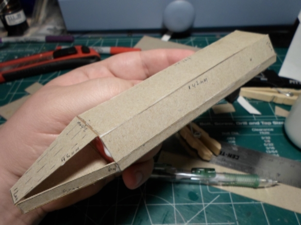
Yeah, not so much. I have started working on the next sections. Firstly there's the cannon mounting under-carriage, the part that holds the reaper cannons in Wing Commander 3.
You ever start to work on something and think it'll be super-easy and you can just zip right through it, but once you start working on it, you find out it's actually way more difficult then you thought it'd be? Well, that was this part in a nutshell. Cut 2 side parts so they line up with the under side of the body and the forward boom, what's so hard about that? Simple, I have no formal 3D design experience or training. So because of that I had to re-cut the sides a couple times after I found I had not measured properly.

For detail and variation I took a pencil and darkened the inner spaces of the under carriage where the reaper cannons would be placed.

And then, there is the power-plants... er missile bays.... er... whatever the boxy shapes on the sides of the main body are. This proved to be more challenging then it first appears.
The initial shape was easy enough to accomplish, measure and cut the upper and lower sections as they appears in the line art. I had to do some interpretation to make the side and inner-section. There's little enough I can say about the sides that would really help any aspiring crafters. I had to estimate my measurements, cut a piece and test it. Find out I was wrong, and try to correct it with a new version.

No the real challenge was the scoop intake covers. See, it's an angle that extends in 2 dimensions, backwards relative to the body, and outward relative of the body. It's something that isn't immediately apparent from the 2D line art. So I had to cut and fit the ram scoop cover about 6 times before I got a sizing that fits.




Friday, December 18, 2015

F-103 Excalibur Space Superiority Fighter erm... had an accident.

Well...... ssssssshhhhhhhhhhhhhhhhhhhhhiiiiiiiiiiiiiiiiiiiiiiiiiitttttttttt! I have to start over on the mock up. I was gluing the bottom panel of the body in place. What I didn't realize was some glue had leaked out of the body and onto my work space. So when it dried it dried to my work space. I went to pick up the body, and in the process tore it apart.

Well this is why I started with cardboard. So I could make these sorts of screw ups and not have to pay through the nose for it.

Still, this sucks.
 

Wednesday, December 16, 2015

F-103 Excalibur Space Superiority Fighter Part 5

Okay, so I've got a notable update today. I haven't finished taking measurements yet, and I'm still working on that front. What I do have is a partial card board mock up of the forward fuselage. This is little more a simple mock up with the basic measurements I've got already. Not complete. This is meant to be an exploration of the construction of the finished model. As one example, I've already encountered one mistake. When I figuring out the parts based on the measurements from the line drawings, I thought the triangular section that would make up the side of the cockpit section was a right triangle. Well, it's not. So the original part I made based on the measurements didn't fit in the space.
 
The mock isn't so much meant as a means of exact build, but rather a means of low-cost construction that will lead back into additional design work. As I've said I do not have design experience or training. Add to that my rather dubious knowledge of geometry... yeah. Up hill battle with a fairly substantial learning curve involved. But that's also the appeal of the project for me.


 More then anything else, the mock-allows me to work with the physical design and understand how sections work with each other and see details that may not have been apparent in the line studies.

Monday, December 14, 2015

F-103 Excalibur Space Superiority Fighter Part 4

I don't have a whole lot to show this time. Because of the nature of this project, it's going to have several phases of intense work for little immediate result. This is one of those phases. Where I get to go through the line images I created, and begin extracting measurements. And measurements. and measurements. So far I have 25 measurements and I'm only... eh.... 80% finished. With the back view. I still have the front, side, top and bottom to do. And the top and bottom are going to be the big data-dumps! For reference, understand that the entire space the rear view takes up is 87.5mm high by 182mm wide while by comparison the top view occupies a space of 170mm wide by 305mm long. And the top and bottom views have a lot more detail then the rear. Still, gotta get started somewhere right? So what do I have to show today?

Well, this:

Friday, December 11, 2015

F-103 Excalibur Space Superiority Fighter Part 3

So I've got to give a shout out to a fellow modeler with a Wing Commander obsession. Whiplash, thank you for your help and encouragement sir!

So what am I thanking Whiplash for? Well first off, Whiplash is a member of the Wing Commander community I met via the wcnews.com forums when I posted work on my Excalibur there. Whip was directed to my thread where he then provided some guidance to me based on his own project. Whiplash had done a similar project to my own a bit of a ways back in that he built a model of a Wing Commander fighter. He chose to base his project on the Hellcat V general purpose fighter and he chose to work in wood rather then plastic, but he was able to provide some extremely valuable insight in translating information from 2D designs and images to 3D designs and plans. 

The single biggest thing he told me about was how the limits of the technology used in the games at the time does not lend itself well to gaining measurement for production of a model and instead suggested I use art work for my basis rather then in-game screen shots while using in-game cut scene shots to collect detail information. So to that end I assembled a pair of fairly substantial libraries of artistic references and cut scene frames for the Excalibur.

Beyond all of that I did start crunching some numbers for the model again based on the Warbird images. I've decided I'm going to scale back a bit for the project and rather then do a 16" long model, I'm going to do a 12" long model instead. I've done lots of small scratch build jobs before, but never a full blow from the ground up total scratch built model before. And I'm thinking about doing some lighting effects in the model as well. So the 12" version will be easier to manager and I think closer to my skill set at present. I want to challenge myself, not waste my energy and materials.

So, I took the warbirds image and pulled it into Photoshop where I upped the size by a factor of 6 so I have some room to work and make notes. The image is small enough that I will be forced to 'interpret' a lot of details, but that's what the reference library is for. With the image in Photoshop I started working out some numbers. I had to go way back to Algebra and Geometry to remember how to work with scales and conversions for this and I'm not totally sure my math is accurate. So if anyone who actually knows what they are feel see a mistake, please point it out.

Here is what I have:

Whiplash has also provided me a break down how he went about translating the sizes of the 2"x2" thumbnail images into something large enough to be used. It helped shed a lot of light on the approach and the hows of why it worked for him. It also gave me some inspiration for a new direction to take the project. As he explained, trying to measure the warbirds image that is less then 2" long is only going to lead me to compounding errors from earlier in the project. Don't ask me why, but that clicked with me in regards to digital graphics. I'll explain:

See in digital graphics you have 2 types of graphical engines each with their benefits and minuses to design. The first is known Raster graphics, or sometimes referred to has bit-map pictures. This format uses individual colors dots to render an image. The more dots you have in a given space the sharper the image can be. A line is simply a series of dots of comparable color. This format has the advantage of being capable of storing far more graphical information and being the foundation most directly based in traditional art work so many of the concepts from that medium translate to this format. The second type of graphic is known as Vector graphics. These use mathematics to form shapes rather then recording each individual position of every point contained in the image. This has the advantage of being vastly easier for a computer to deal with but doesn't translate from math to art very well.

Why am I bringing this up? Well, the two graphic types have another consideration between them, how well they scale up or down. See a bit-map can only be scaled by either adding or removing details. How the program add details will effect how well the image scales up, but generally you can only scale a bit-map image up about 50-60% before you start seeing a noticeable loss in sharpness as additional quasi-random extra material is added.

As an example, look at the corner on the right side of the Excalibur image where the forward section of the fuselage meets the side of the wing and side mounts. On the 1 1/2" sized image it's moderately decent.  


 But enlarge it about 400% (so that the over all image would be about 4.5" long for reference) and suddenly it stops looking anywhere near as sharp.
Vector Graphics however, because they are mathematically based can scale infinity. The program simply remaps the location and calculates what's between the points as needed.

So why did I just explain all of that? Well you gave me the idea to start with a series of vector graphics, based on the Warbirds images, then upscale those vectors to the size I need them. Since the vectors expand infinitely, there's no lose of detail in the process. I started with just tracing the major sections visible on the Warbirds image. I did some digging and found my hard copy of the Wing Commander 3 stuff and scanned the warbirds images at an obscenely high resolution of 2700 dpi then pulled that scan into photoshop (as an aside, it's always a challenge working with 5"x2" image that's a staggering 400megs :eek: in size) and went to work with the pen toll to generate the vector graphics. the high resolution pulled out some details, but the size of the original image simply doesn't have a lot of detail to start with.

Remember how I said enlarging a bit-map image is done by adding material? Well scanning a printed image at such a resolution results in basically the same thing. End result? I could trace out the body, the engines, and the cockpit. The rest... eh I kind of had to take some artistic license with those.

Remember that library of images I assembled of the Excalibur? Well I used that a lot in this process. I primarily referenced the "armada" rendering of the Excalibur for filling in the details that were lost in the up-scaling of the scan. So after a couple hours worth of work, I assembled the following top-down image of the Excalibur with (website friendly version displayed. If you want to grab the 300 DPI version it's linked here)

I mentioned that these are first passes, why is that? Well... it's because they don't match up exactly with each other. It's too late for me to go into all details but as an example. The widest part of the front boom where the cockpit is, it is widest on the front view, narrowest on the top view, and just slightly narrower in the bottom view.

So what does this mean? Well, it means I have to go back, pair up the line art pieces with each other and decide which part of which version I want to take as the 'correct' version. While the web version of the image above sizes out to be about 4" wide, I want to build a 12" model from these designs. So if I scale everything up by a factor of 3, and I have one part from the bottom that is 1mm wider, then the same part from the top view, but the rear version is 1mm to the left, I'll wind up with a part that started out as a rectangular cube but when built comes out as a lop-sided rhombus. So guess what I get to do over the next few days....


Wednesday, December 09, 2015

F-103 Excalibur Space Superiority Fighter Part 2

When I built the paper-craft version I used Pericles' paper-craft designs for the Vampire. The... I don't want to say the word but it's the only one I can think of, the 'problem' with Pericles' plans is they are quit literally the in-game model transferred to paper, which while it makes a game-accurate model, I'm shooting for something that is more universe accurate. The best example of what I mean on the Vampire can be seen in the nose:

If you look at the art work for the Vampire:
You can see it has a pair of twin-linked cannon barrel barrels (I want to say those would be the partial guns if memory serves based on placement).

But compare that to the nose of the in-game model:
You can see how the two barrels and assembly have been condensed down into what... well whatever that is. It's just something that didn't get translated from the artwork to the model or vice versa. Also the in-game vampire have a much leaner body thus appearing longer then in the art work.

For the Excalibur I want to go for display value. So I'll be interpreting and adding additional details, but I want to stay closer to the Wing Commander 3 version of the craft, but if I come to a point where I have a source of data from in-game compared to a source of data from say universe, unless I have an explicit reason to do other wise I'm going to take the source from in-universe as more accurate.

As I progress through the project I'm going to be posting a lot of information regarding how I go about things, how I got sizes, how I build parts, ect. I'm going to do this for a variety of reasons, and not all of them personal. As I said, I have no 3D design or architectural experience what so ever, I toyed with Miya for like 20 minutes once about 20 years ago, and have never had enough of an interest to go back into it. I've built.... the dark gods only know how many kit-models and I've converted hundreds more over the last 30 years, so I have a mind for "unfolding" things from their 3D construct to a 2d part. Still, there is a difference between knowing how to unfold an object and knowing how to build it.

So I will be posting pretty detailed progress updates on the project as I go both for a personal record so I can come back to it and see what I did, and to give people with more knowledge then I an opportunity to look at my process and provide feed back. And finally I'll post the detailed info as a basis for anyone else who wants to give it a go. I seek to inspire after all.

F-103 Excalibur Space Superiority Fighter

Wing Commander 3: Heart of the Tiger is one of my favorite games of all times, and I absolutely loved piloting the Excalibur fighter in the game. So this is my effort to scratch-build a large scale (about 16" long) model of it. This is going to be a long term project. So this is going to be my project thread on here as I work through the project.

I did a paper-craft version of the F-109 Vampire recently, and that really rekindled an old interest I've had to have a model of the F-103 Excalibur.

Here is an image of the finished Paper-craft Vampire:

 And if you want to check out more images of the construction process of it, check out the album:
Paper craft F-109 Vampire

I'll warn everyone now, this is going to take a while to complete. It will also be my first totally scratch built and self-designed model. The real challenge... I have no actual 3D design experience or systems. So I'm doing this all as I figure it out. Who wants to go on an adventure?

First thing I did was load up Wing Commander: Secret Opts and swap the in-game Excalibur with the Panther Fighter, that way I could control the fighter while I took screen caps of the fighter. So I took head-on shots of the craft from each of the axis angles. I then assembled those images into the collage you see here in Photoshop. I then used the full sized print out to gather measurements of the craft. here is the first batch of measurements.


This is the full size print out I assembled of the top-down shot of the Excalibur. Nothing particularly fancy here. Took the top down image, up-scaled it until it was the size I wanted (about 16" in length), and then printed it out. Cut the parts out and glued them together to get one sheet. From this I'm able to take measurements, which I record in the collage in photoshop.

Wednesday, November 11, 2015

Project: OZ-13MS Gundam Epyon Part 8

And it's name is Epyon. So here we have the finished OZ-13MS Gundam Epyon on the Libra Base with lighting effects.This was an educational project and I'm glad I undertook it, even if the final result isn't quit what I had envisioned when I began. This is the root of why I run this blog, the analysis and understanding of my projects.

So with a finished project, what problems did I encounter working on it? Well the legs are the first thing that stick out. I mounted the feet too far apart on the Libra base, so this forced the legs further apart. This creates a bit of a bow-legged appearance and hurts the final version of the model.

I had previously talked about the issue with the back of the model, but I want to touch on it again. The root cause of the problem is that I didn't do as good a job of planning for the project as I really could have. The back of the torso has an open slot intended to allow the hips to flip back and allow the legs to comes over the back in order to become the heads of the dragon mode mobile armor. But I removed the ability of the model to transform for this project. So the end result is I basically have a hole in the back of the model. Looking as this, it is pretty straight forward what I should have done. That is first put a layer of styrene in to cover the space from inside, and then add additional pieces of stryrene to fill in the space. Sand it down so it meshes up with the sides of the waist and finally paint it to match the color of the kit plastic.

Monday, November 09, 2015

Project: OZ-13MS Gundam Epyon Part 7

So now we're starting to wrap up this project. Wow has it ever been a trip to get to this point, from experimenting with casting clear resins, to building new sections to replace what would otherwise be moving joints, to modifying existing parts to accept new components. Now it all begins to come together.

It was a fairly simply matter to cast a new part for the chest gem. I simply attached the original gen sticker to a segment of styrene tubing, and then made the mold based on that part. Unlike casting the saber effect, this was a far simpler affair and required only 2 attempts to get right including embedding the LED in the part.

 Of course putting everything together... that was more of a chore. Here you see the majority of the final connections being made in the chest cavity.
 I should have thought of this before, but alas I did now. The way the model is intended to transform, there is a slot in the back where the hip/waist assembly would fold up allowing the legs to flip over the back. Since I removed the actual transformation mechanism, this space was no longer needed and I really should have covered the slot with styrene and painted it to match the rest of the waist. Sadly this wasn't something I thought of before hand. So if you look closely you will see the wires in the finished model.
 "What? you think I was going to skip arm day?"

I had to use pressure clamps to hold the body together while the glue set. This is largely it. Next time the finished project.


Wednesday, November 04, 2015

Project: OZ-13MS Gundam Epyon Part 5

I knew from the start that the giant beam saber was going to be a critical component of the finished model. I wanted the entire saber effect to glow bright green and that was going to be a challenge. At first I toyed with the idea of inserting a flat LED into the base of the saber effect and running wires through the hilt and into the hip.
OZ-13MS Gundam Epyon from New Mobile Report: Gundam Wing, Beam sader effect with an LED placed into a cut out in the base.
While there was ample space to place the LED in the base of the saber effect, there was the issue of connecting it to the power source. I felt a bit nervous about trying to solder the connections so close to the hilt. So I decided to go with resin casting with the intention of being able to embed a string of LEDs into the saber effect. 

Yeah... working with translucent resins and dyes is trickier then it first seems.
This was my first attempt with green dye and supposedly clear resin. Yeah.... apparently when this company says 'clear' they actually mean 'amber clear'. So adding green dye produces this blue color. Believing I had somehow screwed up the cast, I attempted several more casts with this type of resin, and they all gave me similar blue colors. I turned to Jeff over at Dragon Forge Design for some advise on resins for this purpose. He pointed at at Smooth-Ons Smooth-Cast 327 series of tintable resins. So I ordered a trial pack and the sample pack of their 'So Strong dyes'. Getting tired of trying to do green, and wanting to try something in red. So I tried again with 1 once of the Smooth-Cast 327 and a drop of red dye. And I do mean 'a drop'. I took a tooth pick, dipped it in the red and allowed a single drop to roll off the tooth pick into the resin before mixing it. This combination produced the following:
My a later attempt at casting a replacement saber effect for the OZ-13MS Gundam Epyon from New Mobile Report: Gundam Wing with clear resin. This time I tried red dye.
It is a very solid and very nearly totally opaque red. It looks kind of cool, but it wouldn't work for my purposes. I did try putting a super-bright LED to the red resin just to see how much light did come through. In a totally dark room, with not other light sources what so ever, it just barely glowed at all. Far too dark for what I was going for. So I went back to experimentation working with differing concentrations of dye in the volume of resin. I used rock molds to avoid wearing out the saber effect mold I had made.

I had to expirament with different casting mixes to get a clear color that I felt would work for the saber effect of the OZ-13MS Gundam Epyon from New Mobile Report: Gundam Wing.

I finally settled on an approximate ration of resin to dye by mixing up 1 1/2 ounces of resin and adding about half a drop of dye from the very tip of a pin. Yeah when they decided to call there dye series 'So Strong' they picked the right name. With a good ratio figured out, I went to work building the LED array to embed in the cast. I settled on a series of four flat LEDs to get the proper brightness. It took some finagling, but I managed to get the LEDs roughly in the middle of the mold and the resin properly cast around them.

The finished replacement beam saber effect for the OZ-13MS Gundam Epyon from New Mobile Report: Gundam Wing with embedded LEDs.

The finished replacement beam saber effect for the OZ-13MS Gundam Epyon from New Mobile Report: Gundam Wing with embedded LEDs.

Monday, November 02, 2015

Project: OZ-13MS Gundam Epyon Part 4

"Hey Zecks, Zero is saying you have no future. Is Epyon telling you different?"
So today I'm talking about the head. Since this a basically humanoid model, you know if you ignore the large wings, the devilish appearing armor and the whip arm that is, the head is a major focus point for the model. Because of this I wanted to put extra care into it's production and preparation.
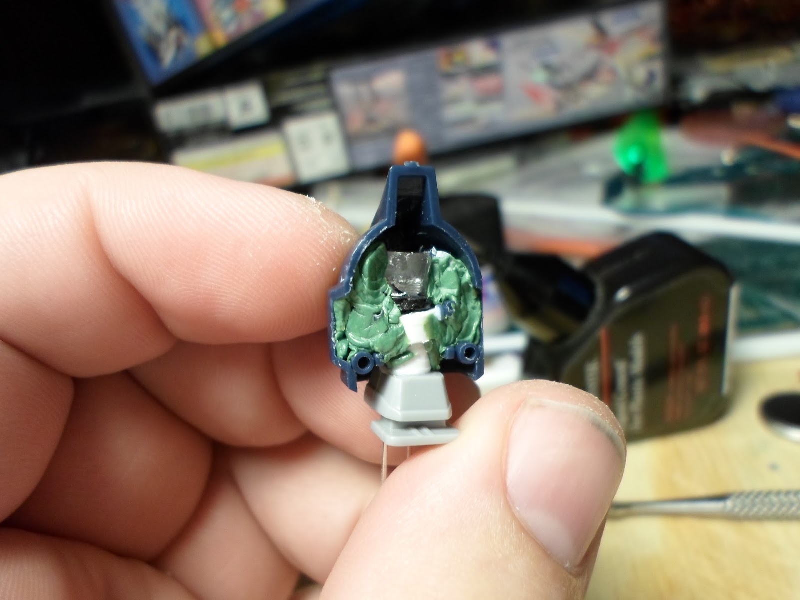
The first challenge was making space for the LED in the head. I went with a flat topped LED because it's easier to orient. To help direct the light more I painted the back side with silver pant and then came back with several coats of black paint. I wanted as little light leaking out as possible. In order to accommodate the LED in the head I had to cut away the mounting ports that would normally hold the parts of the head together. The next big trick was building a new neck brace for the head. 

Normally the head sits on a ball joint, but with the LED in there the joint would have have to go. So I went to work with some styrene tubing and built a new mounting brace. I took extra care to ensure the negative and positive leads on the LEDs are on the right and left respectively. This way it was going to be easier to connect everything later one. 


Once the new neck was built, I went back in with some Kneadatite modeling putty and filled in the space. I do not want this LED to move at all.

In order to keep the right look, I went in with some paint markers and marked around the eyes of the green clear plastic. This creates a shadow around the eyes and helps to keep the 'sinister' look of it.

Friday, November 14, 2014

Project: OZ-13MS Gundam Epyon Part 3

Battleship Libra, that is the topic of today post. More specifically the construction of a stand that is intended to represent a piece of the battleship that will act as a base for the Epyon model and provide a location to house the majority of the electronics for the finished product. Now previously I had a flat panel with some bracing and a pair of raised sections to house the switch and the battery pack for the Libra base.

The bottom of the base for the OZ-13MS Epyon Gundam.
The base for the Epyon Gundam.
So obviously the next big step is adding the sides for the base. The sides are made up of alternating sized triangles, the wide sections on the longer sides, and the corners being covered in a thinner triangle shape. So in theory I should just be able to cut out the 4 wide triangles, and the 4 narrow triangles, glue them together and call it a day. Right?

Well, in theory yes. That is what I would need to do. See, here’s the thing: Reality isn’t theory. Here’s a prime example of this  concept in action. When I cut out the shapes I used the measurements for the two-dimensional shapes, and I didn’t take into account the dimensions of the depth of the part. This isn’t necessarily a bad thing so long as I’m willing to do the work on the next stage. 

The problem the lack of consideration for the depth measurement creates is one of sides not lining up the way that you would expect them to in theory. 2+2+2= 6 yes, but 1.99+1.99+1.99= 5.97 and that’s where the problem comes in. This construct has 8 sides. 4 of those sides are supposed to be the same, while the other four are different from the first four. So using the previous example of 2+2+2=6, well now it is 7.0625+1+7.0625+1+7.0625+1+7.0625+1=32.25. Again, in theory.
 But lets say it becomes:  7.062+1.01+7.0725+0.92+7.0425+1+7.1625+1.09=32.3595.
A difference of 1/20th of an inch one way or the other on each piece amounts to more than a 1/10th of an inch of difference in sizes.

But remember, these are pieces that are being assembled into a three dimensional structure. Once the parts are attached to the structure, it’ll be really hard to cut the parts. So in this particular case, I’m advocating to take more off then leaving too much. Which is what brings me to this:

Building the Libra Starship base for the OZ-13MS Epyon Gundam. The pieces don't line up perfectly.
The Libra takes form.

In building the pyramid structure I was able to mostly marry up the edges in such a way that just a little bit of sanding will be needed to hide the seam. On this last facing however, this is where all those .02 and .01 inches worth of difference finally added up to close to a quarter inch of gap. I had to slide in an extra segment of sheet styrene to fill the gap and even then there is still a sizable space between the parts. So I will need to fill the space with a putty and sand it down.

With some advice from a friend at Hobby Town I picked up a tube of Tamiya Putty white and went to work filling the spaces. The putty is really hard on the skin, and it’s best to wear gloves when working with this stuff. Beyond it being best to wear gloves, using the putty is very simple and straight forward. Apply a portion of putty to the seam and then smooth it down with your finger tip. Let it sit for 24 hours so that the putty has a chance to cure and harden properly. Once it had cured I just needed to come in sand paper and sand it down smooth. I started with 200 grit sand paper and worked my way up to 1200 grit for a smooth finish.

The next step was scribing the lines of the panels . If you look at the image of the Epyon perched atop the Libra, you can see the divisions between the parts of metal that make up the surface of the ship. These are the panel lines.

The first step in this process was to mark out the lines. This sounds like it would require a lot of measuring, and in truth there is a lot of allowance for that sort of detail. But once everything is said unlike the process of building the pyramid itself, this really had no reason to be such a detailed process. So the only measuring I did for this part was the distance from the apex of the pyramid down the sides. I marked out lines with an interval of 1.5”. So 1.5” from the top of the pyramid to the first line, 1.5” from that line to the next and finally 1.5” to the next. I used a blue fine tip marker to draw out the horizontal lines that will be etched into the surface. I then went in and basically put in random vertical lines to mark out various sized plates.

After smoothing out corners with Tamiya white putty, I came back and marked out the panel lines for the Libra Battle Ship base for the OZ-13MS Gundam Epyon

Once I had the lines marked out, I came back along with label tape and lined the tape along the horizontal lines. The label tape is that plastic sort of tape used in those label maker guns. This tape provides a hard edge with an adhesive back to it that can be stuck on the surface of plastic. With the tape applied I then went to work with my scribing tool. I went for a depth of 5 passes with the scriber. This gives a really solid panel line. Once I had the horizontal lines scribed I went to work on the vertical lines.


Monday, November 10, 2014

Project: OZ-13MS Gundam Epyon Part 2

Creating the new beam saber. This is really the crux of this entire project. Most of the 1/100 scale GunPla models come with beam weapon effects molded in a tinted plastic, in the case of the Epyon it is molded in green plastic. But I want to be able to light up the plastic. I had previously tried to accomplish this by carving out a space for the LED inside the saber effect and mounting the LED at the base of the saber effect.

I initially tried cutting out a hole in the Epyons beam saber effect to put an LED in the piece.
I cut out a hole in the beam saber blade for a square LED.
 It does work… sort of. But it also brings up a lot of additional problems, the biggest being how do I solder the wires when the LED connections are practically on top of the plastic handle itself and the handle isn’t actually wide enough to survive being drilled through the length to pass the wires through.  So I decided to cast the beam saber effect, and the saber hilt in tinted resin. This way I can physically imbed the LED inside the part, rather then having to cut up the part to fit the LED. I can also pre-assemble the LED, resistors and lead wires before embedding them into the resin and then just pass the wires through the cable tube that actually comes with the model.

 Now, casting is a surprisingly simple process that can become incredibly demanding over very simple aspects. The Epyon’s beam saber with the saber effect when assembled is a design that emphasizes it’s lateral details while having relatively little vertical details. This is of relevance to the mold making process. The silicone rubber will fill in any space that isn’t sealed off. For instance, where the green plastic beam effect sits in the hilt, the hilt is raised away from the saber effect so if the mold is laid out width wise the rubber would encapsulate the saber hilt and fill that void between the hilt and the saber effect creating a wasted effort of a mold. It would be wasted because I would then have to cut apart the mold in order to remove the original part very likely ruining the mold in the process.

So there are 2 ways to make a mold for the Epyon sword, the first is make the mold with the hilt and saber effect mounted depth wise. This allows the lateral details to be taken very well. The second way is to mount the parts laterally and make a shallow mold. The challenge with this second approach is I have to make sure to filling any spaces that will cause the  rubber to encapsulate the original parts.
I made my first effort to create the mold by mounting the saber in the rubber depth wise.

Initially I made a mold for the Epyon Gundam's beam saber by mounting the saber deapth wise.
The first mold setup for the beam saber I made.
Well I ran into another problem with this approach, well 2 problems actually. First, it takes more rubber to make the mold like this. And by more, I mean close to 30% more. You really can’t make a silicon rubber mold that is narrower than 1” and with as long as the Epyon beam saber part actually, it’s close to 6” long with the larger saber effect; the mold really needs to be 4” wide, if not wider, in order to keep the blade straight. So making the mold depth wise simply didn’t work out and with that I needed to create a new mold this time shallower and wider.  I used some clay to fill in the spaces that would otherwise be filled by the rubber.

So 2 days later, I had a working 2 part mold for the Epyon beam saber that I can now cast in green tinted resin and embed an LED in it to create the light up saber for the mold. Things are looking good. So I mixed the resin, picked up a bottle of green dye, mixed in a couple drops of green dye to tint the resin green, poured the green tinted resin into the mold, put the LED in the base and then put the green tinted resin filled mold in the pressure pot, sealed up the pot, pressurized it, and left it sit for 6 days so the resin would cure. Yes, the resin I tried this with has a 6-7 day cure time.

This incredibly long cure time is actually a bit of a good thing in this case. When you mix epoxies like resin you tend to mix in air that create bubbles in the resin. With opaque resins this is a non-issue, but with transparent resin it create some visual headaches. So there’s 2 days to deal with this and in both cases it takes a little time and control of air pressure. The first option is to perform a process called “Vacuum degassing” where you put the resin into an air tight chamber and suck all of the air out of the chamber. This causes the bubbles of air in the resin to be pulled up out of the resin. The second option is literally the exact opposite, that is putting the resin in a reinforced chamber that is air tight and increasing the air pressure to between 50 and 60 PSI. The increased pressure crushes the bubbles out of the resin. So both approaches have the same effect, to force the bubbles out of the resin.

So, a week later I depressurize the pressure chamber, pop the top, pull out the mold, separate the two parts, pull out the part that was cast from green tinted resin and find… that it’s blue.

The first attempt at recasting the Epyon Gundams beam saber turned out blue... somehow.
So... how does it come out blue?
And has you can see it’s not even like a blue-green or a sea-green sort of dark green… no it’s blue. So… yeah. What the heck?

Friday, October 31, 2014

Project: OZ-13MS Gundam Epyon

The Gundam Epyon stands atop the Battleship Libra with its saber blazing as it prepares for battle.

The Gundam Epyon: the demon to the Wing Zero's angel, Trieze's ideal of chivalry. The Gundam Epyon was first hinted at only a couple episodes after the introduction of the Wing Zero but its’ true ability would not be revealed until much later in the series. A suit designed for dueling and engaging the enemy face to face, the Epyon was originally armed with an over charged beam saber and a segmented whip that could be heated and used to cut through even heavy armor. Like the Heavy Arms Custom Kai, I built this model years ago, and like that I'm looking back at my work then and thinking "Wow... I didn't have a clue what I was doing back then."

This project is going to involve several things and major phases. The first major phase will be the "scratch building" phase. If you look at the image at the head of this post, you can see the pose I’m going for with this model. Epyon, standing at the apex point of the Libra Battle station, with its beam saber powered on, its search eye activated and its eyes glowing. Since I’m going to build LEDs into the model I will need a power source. When I do lighting projects I like to have the battery pack accessible so that I can replace batteries as I need to. So, the battery pack will be placed on the underside of the base along with the control switch. To keep with the image, I’m going to be fashioning a base to resemble the Libra battle ship to house the majority of the electronic components.
Epyon is online, ZERO system active! The Epyon's eyes, search eye and Chest jewel will glow with the use of LEDs.
The Second phase will be the “casting” phase. One of my objectives with this project is lighting up the beam saber and the chest mounted combat eye/camera. To accomplish this, I’m going to recast the parts in green-tinted transparent resin. By being able to cast the parts, I can embed an LED in the resin and then connect those LEDs to a power source to illuminate the resin. That is my hope, at least. Time will tell if I am able to follow it through. With the base, the cast parts and the lights, I think the entire model will work well enough without the means to move the arms around. I think the trade-off will be worth it though.

The third phase will be about modifying the model to become a mono-pose setup. This is going to involve replacing the poly-vinyl joint caps with styrene pieces that will be glued into place locking joints into the configuration. The other part of this will be modifying parts of the model to accept the wires and LEDs. For instance, the head would normally use a poly-vinyl cup that would sit on the ball joint of the neck. That will be modified to be styrene, and thus not pose-able, so that I can pass the wires from the LED through the neck.

The last major phase of the project will be the assembling and detailing phase. In this phase I will be using pigment powders and paints to add details such as shadowing and panel lines. I’m going to use a sheet of decals from the master grade Epyon to add some additional detail to this model.
This project is really turning into the prototype effort for my Wing Zero project. I originally settled on this project with the intention of just lighting up the beam saber, then that turned into lighting up the eyes, which turned into lighting up the chest gem. The building of the Libra base was more a choice of doing something aesthetically pleasing, more than just building a box for the model to stand on.

So the first thing I went to work on was designing the base that will house the electronics and the batteries. For that I turned to a friend of mine who is an architect (helpful hint for modelers who scratch build: If you don’t know architectural design, become friends with someone who does).  I explained to her that I wanted to design a base that was effectively an eight sided pyramid with the even sides being small and narrow and the odd sides being wide. We exchanged a couple more notes and she came back to me with this:

the parts lay outs and size information to build the base of the Battleship libra for the Gundam Epyon.
While it’s fairly simplistic, it gives me the information to start work on the base with my own skills. After a few hours of cutting and gluing I came up with this:
The base that will serve as the bottem of the Battleship Libra to mount the OZ-13MS Gundam Epyon and hold it's electrical componenets.
The larger box in the middle houses a 4-AA battery pack, while the smaller box to the side of that box houses a single pole switch that will control the entire circuit in the model. This is a fairly simple circuit and anyone who has any experience with electronics can build it. That isn’t the real challenge for this project, however. The challenge is changing the model to accommodate these changes, and creating the new parts.

Next time I’ll be talking about creating the molds for casting the new parts.

Friday, October 10, 2014

Project: Heavy Arms Rebuild #8


“This is battle 001, Pilots name: Trowa. Just for the record.”


So, the Heavy Arms conversion is complete! It’s an odd sense to look at the finished project, comparing it to the original kit design and note how much and how little changed between the anime version and the Endless Waltz version. The short version is that there are lots of little details that were changed (I’ll talk about them later), while the major stuff remains largely the same. The basic mech design stays the same, which is really what made this entire project possible in the first place..

The Heavy Arms Custom as it appeared in Endless Waltz compared to the anime version Heavy Arm.
Now remember: my goal for this project was to convert the Heavy Arms Custom Kai into something more resembling its anime counter-part. There were several places where I decided to keep the Endless Waltz design, either because changing it would be considerably more work than I was prepared to commit to this project, or because I liked the redesign better. There was really one part of it that I needed to change from the original kit and that was the mounting for the second set of missile pods on the legs. Everything else was either a case of gluing a part in place so it’s not an opening panel (The backs of the shoulders) or of building new pieces to be added on to the existing model. I’m going to talk more about these points in my project review but I know not everyone wants to watch videos all the time, so I’m going to cover the same points here in this post as well.

So let’s start at the top of the model and work our way down. The shoulders are the first thing that I had to change. The Anime version of Heavy arms had a single compartment in each shoulder that housed missiles, while the Endless Waltz version had 3. One compartment in the shoulder itself, two affixed the shoulder: one in the front that fold open and the second in the back that rotates out. For this conversion, I glued the back panel to the shoulder itself, removing it as a means to deploy more missiles. The second thing I had to do was not insert the plate that had the additional missiles into the forward panel that flipped up from the shoulder. To help make this part look more functional rather than ornamental I added some bracing to the inside of it with a strip of plastic.


1/100 scale Heavy Arms model converted from the Heavy Arms Custom Kai showing the converted sholders.
I needed to fashion an additional micro-missile launcher to go on top of the shoulders. I did this both to be somewhat more anime-accurate and to cover the hole left by the uninstalled  yellow… dog ears? antenna?… whatever the large yellow hook looking things on the shoulders of the Endless Waltz design are. The Anime version didn’t have them and frankly I don’t care for the look of them anyway, so I didn’t put them on. Making the additional missile launchers was pretty straight forward. I used a length of ¼” square plastic and then added some additional 1/16” sheet plastic around that foundation to build up the housing. I cut out the missiles from the extra plates that I didn’t use from the shoulders and then glued the head of the missile to the form. Once those pieces are built it was just a matter of gluing them on over the holes.
1/100 scale Heavy Arms model converted from the Heavy Arms Custom Kai showing the micro missiles on top fo the shoulders.

The chest was a fun challenge, and honestly if I were to do this project over again I would do it differently. What I did this was take the heads of two of the Gatling cannons and cut down the length so that it would sit with in the cavity of the chest and then came back to build in the additional details later, as I talked about in a previous post. Were I to re-do this project I would scratch build smaller Gatling cannons and build up the details around them more in line with how the weapons appeared in the anime.
1/100 scale Heavy Arms model converted from the Heavy Arms Custom Kai showing the converted chest cannons.

One of the changes that was made between the anime version and the Endless Waltz version was the removal of the Heavy Arms single close combat option, a large combat blade housed on the underside of the right arm. So I had to add that back into this model and I accomplished that by scratch building the weapon and attaching it to the arm. I wanted to go with something that looked more like an army issue combat knife as opposed to the large sword style blade the anime version used. This was where I made a mistake with this effort. I made the blade too small.

I made the blade about the same length as the forearm but didn’t compare that to the size of the arm over all, including the hand. So now the blade just barely clears the depth of the hand. I think I have a way to address this shortfall. I’m looking into clear resin casting for a potential project down the line. In conjunction with casting the piece I need for that project I think I can cast a beam effect for this combat blade, the energy blade extending out beyond the length of the arm itself. Future efforts on that front.

1/100 scale Heavy Arms model converted from the Heavy Arms Custom Kai showing the scratch built combat knife under its right arm.

The Endless Waltz version of the Heavy Arms had deployable missiles built into the sides of the skirt armor. The anime version did not have these. To address that difference I simply glued the missile racks into place in their closed position.  As I talked about the legs previously, I won’t go into considerable detail about them now. Originally the legs were meant to mount 2 packs of missiles, while the Anime version of the Gundam only mounted 1 rack of missiles each so I modified the legs to remove the upper mounting points.
I had to modify the legs of the 1/100 scale Heavy Arms Custom Kai to only have one mounting location for missile pods instead of 2.


I made one modification when I built the feet, and that was to fill them with fishing weights. The Heavy Arms model is extremely top heavy and will very easily tip over by itself. To help rectify this I filled the feet with fishing weights to add close to 6 ounces of weight to the bottom of the model.

The Gatling cannon. That’s been an interesting effort. In the Anime the cannon was affixed to a large shield with a sheath that the Gundam’s arm slide into. With the Endless Waltz model the larger scaled double-barreled Gatling cannons are simple held by the models’ hands. In all honesty, they don’t hold it all that well anyway. Both approaches have their problems. The Anime version appeared to be little more than 6 barrels attached to a motor on the shield, with no hint as to where the ammunition was hidden. The Endless Waltz version is much more suggestive of being a functioning item and has space to suggest its actually carrying the ammunition for it. So I wanted to try and bring these two together to make something that looked like it worked. Well… put my efforts under the “partly failed” category. I took the double-barreled weapon, modified to have a single barrel, and then built the sheath for the arm. I took one look at it, and realized that any effort to build the shield on top of it was going to out-balance the entire rest of the model. So I abandoned the effort on the shield. I may come back to this somewhere in the future, and build something like the Gatling cannon and shield assembly from the Katoki redesign of it, which uses a large drum on the back of the Gundam to carry the ammunition.
So that completes my Heavy Arms rebuild project. Next up, the MS-7B3 Gouf Custom with weathering and battle damage.